The primary function of fluid lubrication is to provide a durable film that protects moving parts by reducing friction and wear between surfaces; however, the level of protection provided is enabled by different methods of lubrication:
The reduction of friction by using a fluid can be divided into two basic types: full-film and thin-film. Full-film lubrication consists of four sub-types and thin-film lubrication consists of two sub-types.
Full-film lubrication
- Hydrodynamic
- Elastohydrodynamic
- Hydrostatic-film
- Squeeze-film
Thin-film lubrication
- Boundary
- Mixed-film
We’ll discuss the differences in that order:
Hydrodynamic lubrication
Hydrodynamic, or full-film, lubrication exists when two surfaces are completely separated by an unbroken lubricant film so there is no metal-to-metal contact. The movement of the rolling or sliding action causes the film to become thicker and pressurized, which prevents the surfaces from touching.
When the two surfaces are moving in opposite directions, the fluid immediately next to each surface will travel at the same speed and direction as the surface. If two parts are moving in the same direction, a full hydrodynamic film can be formed by wedging a lubricant between the moving parts. Known as wedging film action, this principle allows large loads to be supported by the fluid. It works much like a car tire hydroplaning on a wet road surface. During reciprocating motion, where the speeds of the relative surfaces eventually reach zero as the direction changes, the wedging of the lubricant is necessary to maintain hydrodynamic lubrication.
The lubricant’s viscosity assumes responsibility for most of the wear protection and additives play a limited role. Although full-film lubrication prevents metal-to-metal contact, abrasive wear or scratching can still occur if dirt particles penetrate the lubricating film. Additional factors, such as load increases, can prevent hydrodynamic lubrication by decreasing the oil film thickness, allowing metal-to-metal contact to occur.
Engine components operating with full-film lubrication include the crankshaft, camshaft and connecting rod bearings, and piston pin bushings. Under normal loads, transmission and rear-axle bearings also operate under hydrodynamic lubrication.

Elastohydrodynamic lubrication
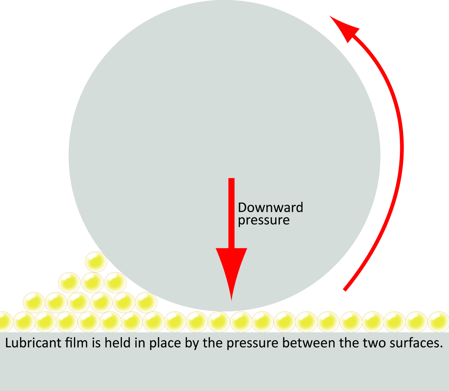
Elastohydrodynamic (EHD) lubrication is another form of full-film lubrication that exists when the lubricant reacts to pressure or load and resists compression, functioning as if it were harder than the metal surface it supports. As viscosity increases under pressure, the film becomes more rigid, creating a temporary elastic deformation of the surfaces. EHD occurs in the area where the most pressure or load affects the component. In roller bearings, for example, the metal surface deforms from the extreme pressure of the lubricant
The lubricant’s viscosity and additives work together to protect surfaces in an EHD system. Anti-wear additives are often used to protect engine bearings in high-load conditions, while both anti-wear and extreme-pressure additives work to protect gears in high-load conditions.

Hydrostatic-film lubrication
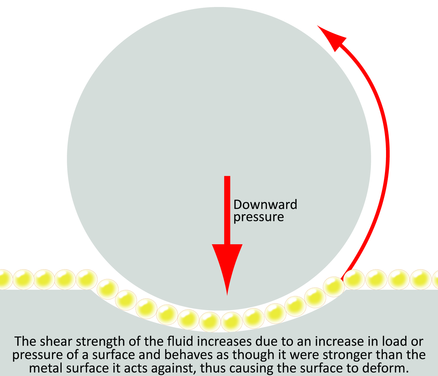
Hydrostatic-film lubrication is a full-film lubrication method common in heavily loaded applications that require a supply of high-pressure oil film. The high pressure in hydrostatic-film lubrication ensures that the required film thickness will be maintained to support a heavy load during extreme operation. Hydrostatic-film lubrication maintains a fluid film under high-load and low-speed conditions, such as those experienced at equipment startup.
Squeeze-film lubrication
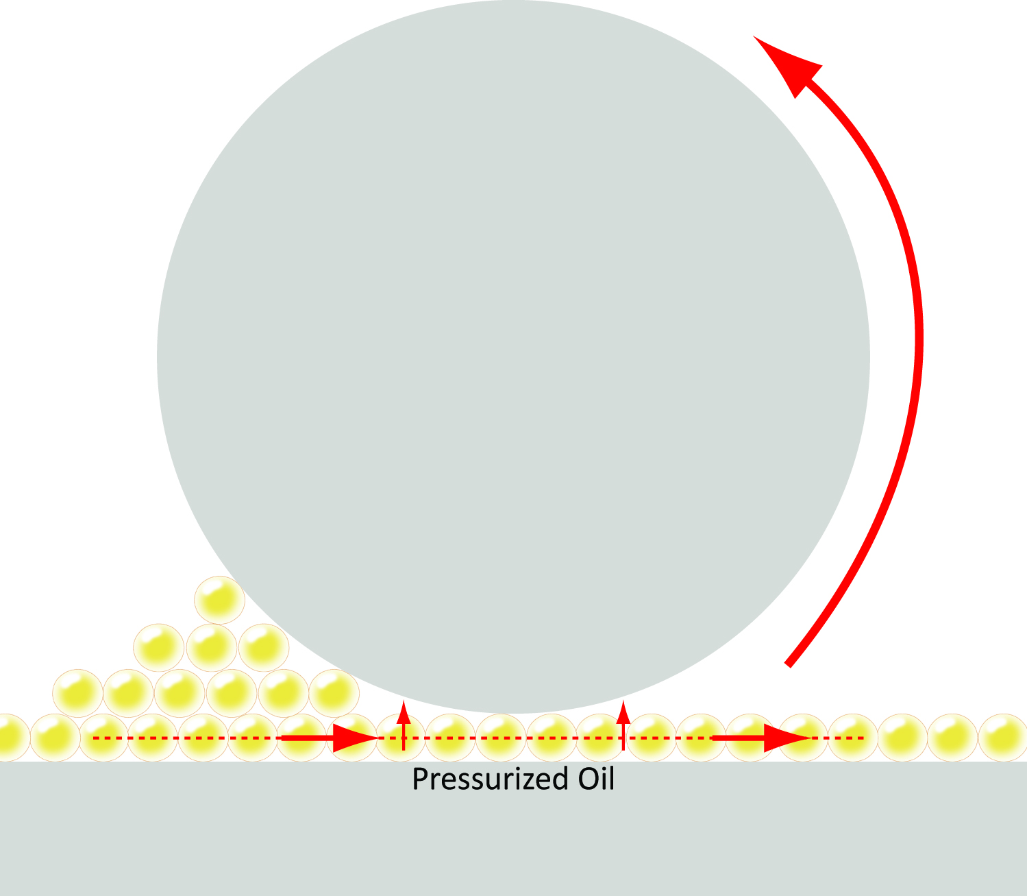
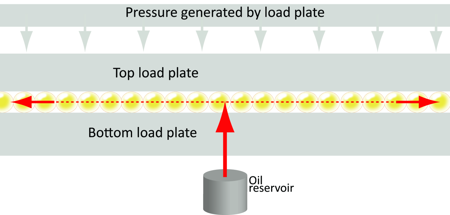
Squeeze-film lubrication is a form of full-film lubrication that results from pressure that causes the top load plate to move toward the bottom load plate. As these surfaces move closer together, the oil moves away from the heavily loaded area.
As load is applied, the viscosity of the lubricant increases, enabling the oil to resist the pressure to flow out from between the plates. Eventually, the lubricant will move to either side, resulting in metal-to-metal contact. A piston pin bushing is a good example of squeeze-film lubrication.

Boundary lubrication
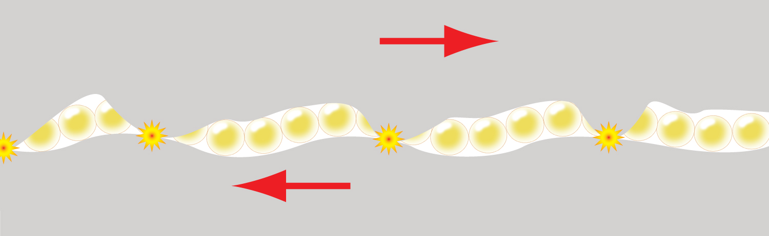
Boundary lubrication is a form of thin-film lubrication and occurs when a lubricant’s film becomes too thin and contact between the surface’s asperities occurs. Excessive loading, high speeds or a change in the fluid’s characteristics can result in boundary lubrication.
No surface is truly smooth, even when polished to a mirror finish. The irregularities, or asperities, on every surface may be so small that they are only visible under a microscope. When two highly polished surfaces meet, only some of these asperities on the surfaces touch, but when force is applied at right angles to the surfaces (called a normal load), the number of contact points increases.
Boundary lubrication often occurs during the start-up and shutdown of equipment. In these cases, chemical compounds enhance the properties of the lubricating fluid to reduce friction and provide wear protection. For instance, anti-wear additives protect the cam lobes, cylinder walls and piston rings in engine high-load conditions, while anti-wear and extreme-pressure additives protect ring and pinion gears in rear axles.

Other lubrication
Mixed-film lubrication is considered a form of thin-film lubrication, although it is a combination of hydrodynamic and boundary lubrication. In mixed-film lubrication, only occasional asperity contact occurs.
Solid-film lubrication is used in applications that are difficult to lubricate with oils and greases. To manage these difficult applications, solid- or dry-film lubrication is applied where the solid or dry material attaches to the surface to reduce roughness. Solid-film lubricants fill the valleys and peaks of a rough surface to prevent metal-to-metal contact. Common solid-film lubricants include graphite, molybdenum disulfide (MoS2, aka moly) and polytetrafluoroethylene (PTFE), also known as Teflon.*
AMSOIL synthetic lubricants are carefully formulated with the optimum blend of the highest quality base stocks and additives, ensuring lubricated components receive outstanding protection from contact wear.

Video transcript: Tour the AMSOIL Mechanical Lab
I’m Mark Nahum, Staff Engineer and Mechanical R&D Manager for AMSOIL, and this is our mech lab. Let’s give you a little sneak peek of what this mechanical lab does for AMSOIL. It is a piece of our validation process for all of the products that we come to market. If I was just a blending facility, I wouldn’t need a mechanical lab to validate my products.
I take fully formulated versions from chemistry partners, I mix them together, and I sell them to consumers. But that’s not what we do here. We take it from the chemical level, we break it down, we make really good formulas, and then we need a place to validate them. Then, we take it down here in the mechanical lab and put those formulas to work in actual applications, whether it’s engines, transmissions, hydrostats, compressors.
That’s what we do here. There’s a difference between those that just blend and those that fully engineer their products. Every project that we work on here in the mechanic lab typically starts with an application out in the market. There’s a problem that we identify, or some customer has a need that is not currently being met by another lubricant.
We start with product requirements. We need a way to gauge success, so we bookend what this product should look like in the end. Then we go to work in our chemical lab. We start mixing formulations together and we use industry standard tests to get us successful on the bench level, but we don’t stop there.
We need to validate that product before we commercialize it. That’s why a mechanical lab is a huge asset to AMSOIL. We put those formulations into real engines. We beat them up, we put them through really long tests, insane temperatures, really heavy loads, all so that we can take all that data and see whether we’ve achieved success.
Now that you have a firm grasp of our validation process here in the mechanical lab, let’s go take a look at the capabilities of each of our cells. Our mechanical lab has three dyno cells. In cell 1, we have a SuperFlow water brake, where we’ll put anything from a small snowmobile engine, all the way up to 1,000 horsepower Hellephant engine. Dyno cell 2, a little more flexibility here, where we’ll run small engines on fixed test stands for hundreds of hours.
We’ll run weed whips and blowers, making noise for hundreds of hours. We have a Midwest eddy current, which is super accurate for long periods of time, where we’ll run small V6 or V8 engines, or we’ll adapt a different tester and run hydrostats from zero-turn lawn mowers. In our last cell, dyno cell 3, we have our SuperFlow roller dyno, where we’ll put motorcycles, dirt bikes, street bikes, side by sides, and we’ll take field data that we collect from the road in the woods doing hill climbs, and we’ll duplicate it on the dyno. Then, we’ll turn up the knob a little bit to reach what we consider sphere testing.
Very rarely do we make decisions around here based on subjectivity. We are in the business of measuring things. That’s how we learn, that’s how we formulate, that’s how we engineer, and that’s how we make products for you to sell to your customers. How do we measure stuff?
We use the tools built into our dynos, which is measuring horsepower, and RPM, and temperatures. We use data acquisition systems to measure a lot of some of those same things if they’re not really integrated to my dyno. Then, what we do is we graphically look at them, and we make sure that if we’re measuring power, or torque, or RPM, when we set up a dyno profile, we want to make sure that that engine is operating that profile every single time and its not deviating. If it’s a deviation from that, then something’s happening in the engine that we need to know about.
We take these measurements to make sure that our test is valid. At the end of this analysis, we shut down the engine or whatever might be on test of time, and then we tear it apart. That’s where the true physical measurements come in. We use measuring tools, and what we’re doing is we’re comparing before to after.
Let’s dive a little deeper into some of the documentation techniques we use in the mechanical lab. We use a high precision camera to document the before and after condition of the parts under test. What we’re looking for is deposits and wear. In this area of the mechanical lab is where we tear everything down.
This is where we physically measure the before and the after condition of everything that we’ve just taken off of test. For example, we have a Twister blower here, and we’re going to measure the difference between the wear that you might find in the cylinder. We’re going to measure the wrist pin. You look at a hydrostat transmission from a zero-turn lawn mower, we’re going to look at the pistons, and the swashplate that builds pressure and propels that thing forward.
We’re going to look at the deposits that form inside that case. You look at this set of cylinders from a snow machine. We’re going to pay particular attention to the bores, the cylinders, and we’re going to measure that profile difference from before and after. You look at a set of bearings on the other side of the table from the crank and the rods.
We want a before and after measurement of the wear to those bearings. The measurements that we take here are of the utmost importance to AMSOIL. We use these measurements to make decisions on new products coming to the market or new technologies that we’re investigating to put into the current products that we have on the market today. We put a lot of importance on this to help you be successful.
Hopefully, you can make it up here someday and see it yourself. But until then, we got to get back to work to work on the top secret projects that I can’t share with you. Thanks for coming. [ MUSIC ]